by Timothy Corey
This article will explain new features of AutoCAD Civil 3D 2018.
1. The AutoCAD .dwg file format has been updated and can no longer be directly opened by previous versions of AutoCAD. This applies to all flavors of AutoCAD: AutoCAD, AutoCAD Architecture, AutoCAD Civil 3D, AutoCAD Map 3D, etc.
2. Offset Alignments with Dynamic Profiles -- Now when you create an Offset Alignment, you can have Civil 3D automatically create a profile for that alignment. The new profile gets its elevations by your setting of the cross slope from the main profile. The new profile can be placed in the existing profile view as a superimposed profile.
Notice how you can set a profile view into which you superimpose the new offset profile and how you can set a cross-slope.
If you need finer control of the cross slope, say you want to slope at -4% within a particular station range, after the offset alignment and profile have been created, click the offset alignment and on the Ribbon, find Offset Profile Properties.
On the Offset Parameters tab, create Cross Slope Regions. Notice how you define the transition between cross slope regions. In the example below, the cross slope will transition from -2% to -4% over 200' of profile, will be at -4% for 300', and will transition back to -2% over 200'.
All that, and it's dynamic. If you modify the main profile, the offset profile will update.
3. Create Connected Alignment -- This feature allows to you create an alignment and profile that "snap" to two other alignment and profile pairs. Think snap-able curb returns.
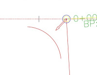
First, Create Connected Alignment.
You will be prompted to select the two alignments that will control your new alignment. Once you do that, you are prompted to "Pick a location for the selected alignment." Select a point that represents which curb return to create. In a T intersection, there will be two possibilities and in a crossing intersection, there will be four.

Note the connection alignments, set the curve radius and the connection overlap. This places a small segment directly atop the connection alignment on each end of the return. The overlap cannot be 0.
Move to the Connected Profile tab and set your profile options:
4. Create Corridor with Multiple Baselines. Used in conjunction with Offset Alignments and Dynamic Offset Profiles, this feature removes the need for Offset Assemblies. Previously, you would use an Offset Assembly in areas where you wanted to control the corridor from a main baseline, but you wanted some subassemblies to be perpendicular to a different alignment. A good example is where you have a bus turnout and you want the curb/gutter/sidewalk to transition, but have the subassemblies perpendicular to the new curb line, not centerline.
This new features allows you to reduce the complexity of Assemblies and to set different frequencies. Because the offset alignment and its dynamic profile are tied to the centerline and the lane subassembly transitions are tied to the offset alignment and profile, the entire corridor is easily controlled by modifying one baseline.
Having different frequencies does cause a small issue with the surfaces you create from your corridor. If you use subassembly links, like Top, to create the surface, you might get some undesirable results:
We get better results using feature lines as the data type when we create corridor surfaces.
5. Relative Elevation Feature Lines -- Relative to what? Relative to a surface! That's right, when you create or edit a feature line, you can tell all or some of its elevation points to be relative to an existing surface. Want the base of the retaining wall 12 inches below the FG surface? No problem.
When you create a feature line, at the point where you tell it which surface to use for its elevation source, you'll have the option to set the elevation relative to the surface.
A nice new detail: After setting the first point as relative to a surface, when you are ready to input the elevation for a subsequent point, the command line defaults to Relative Elevation with the same relative value you used for the previous point. No more saying SU for every single point you want to place on a surface.
As the surface is modified, all feature line points that are derived from the surface relationship will update.
6. Corridor overlap resolution -- In areas where your subassemly links overlap one another, your corridor will suffer from what are commonly called "Bowties".
Well, now Civil 3D will either clean this up for you or let you clean it up using the new Bowtie Cleanup Tools.
To use the automatic tool, be sure you set corridor feature settings to allow cleanup for your geometry type:
Set the Automatic Clear Bowtie Options.
To use the manual tool, pick the corridor in the drawing window. On the ribbon, find Clear Corridor Bowties.
Delight in your results
7. Some of the tools that had been introduced as subscription extensions in previous versions, such as Pipe Sizing and Analysis, Traverse Editor and Plan/Plan Sheet Production have been enhanced and have graduated to become "included" commands in AutoCAD Civil 3D 2018. Congratulations to those commands.
Best regards,
Tim


