
Posted by Timothy Corey, May 18, 2020
Corridor Intersection Primer -- Manually Create an Intersection
Updated for Civil 3D 2018--2021
We first covered this topic in 2014. Since that time, Autodesk has added new capabilities to manual intersection design by introducing Offset Profiles and Connected Alignments.
1. Layout Main and Side Road Alignments

This post assumes you know how to create Alignments and Profiles. We will start the blog having already created those objects.

2. Create Intersection object to lock the Side Road Profile to Main Road Profile
While we won't be using the Intersection Wizard to complete the Intersection design, we will use it as a simple way of locking the starting point of the Side Road Profile to where it intersects Main Road.
Start the Create Intersection command:
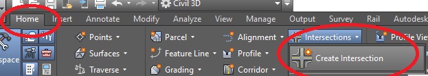
Once the dialog opens, go to the Geometry Details page and uncheck Create or specify offset alignments and then press Create Intersection.

Having created the Intersection, notice that the starting point for Side Road layout profile is now locked to the elevation acquired from Main Road.

3. Create Offset Alignments and Offset Profiles
In order to setup for using Connected Alignments, we need to create Offset Alignments and Offset Profiles. That's what the Connected Alignments will connect to.
In the drawing, select the Main Road Alignment. On the Ribbon, select Offset Alignment.

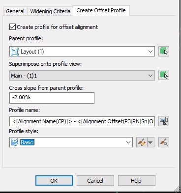
For our example, we only need one offset, on the right, for Main Road. Before pressing OK, go to the Create Offset Profile tab.

Be sure your Parent Profile is set to a Layout Profile, not a Surface Profile. If you want to see this Offset Profile in relation to its Parent, be sure to set it to Superimpose onto that Profile View.
Do the same for Side Road, only we will create Offsets on both sides of this Alignment. Double check the Create Offset Profile tab and be sure the settings are correct.

Which gives us this. The grey lines are the Offset Alignments

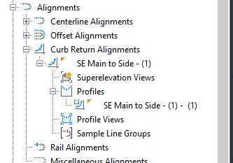
Note in Prospector that each has an automatically-created Profile.

4. Create Connected Alignments
A Connected Alignment is an Alignment that connects to two other Alignments and their Profiles, and acts as a curb return.
Select one of your Offset Alignments, and then pick Connected Alignment from the Ribbon.

Select the second alignment for the connection, then select the quadrant into which you want to place the new Connected Alignment. Press Enter if you like the location or pick a different quadrant.

Set your Connected Alignment name, Curve radius and Connection overlap. Overlap must be non-zero. In the example, we use 10.

Before pressing OK, go to the Connected Profile tab to be sure the box is checked for Create profile for connected alignment. Set your default vertical curve length or K value.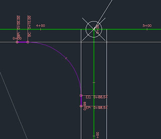


Press OK and inspect your Connected Alignment:

Note in Prospector that this Alignment also has a Profile, but it has not been drawn to the screen.
If you want to view and edit this profile, right click the Alignment, and press Select

Go to the Ribbon and pick Profile View


Do the same process for other quadrants.
5. Create Assemblies
For our example, we will need various Assemblies. First is a full width Assembly, which can model both sides of a Corridor Baseline.

We also need a half-width Assembly, which will model the left side of Main Road through the intersection, leaving an open area where we will model using our Connected Alignments.

And we need an Assembly that has the Curb, shoulder and daylight on the right and the paved lane on the left. This will be attached to a Connected Alignment and will target the two centerlines.

6. Create the Corridor

I like to select my Main Road first, and add other Alignments as additional Corridor Baselines later. We will start with the Full Width Assembly and then add Regions later.

Which produces this initial Corridor:

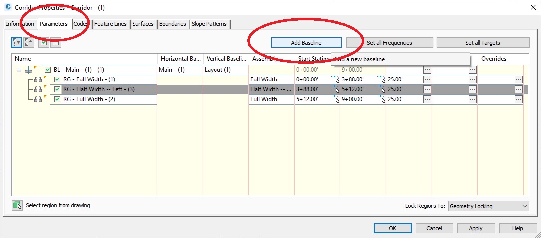
Now we need to create Regions so that we can assign the Half Width Left assembly through the intersection area. Select the Corridor, right click and go to Corridor Properties. On the Parameters tab, right click the Region and select Split Region.

When asked to "Specify station along baseline", select the endpoint at the BC of the Connected Alignment.

When prompted again for a station, select the endpoint at the EC of the SW connected alignment, where it meets the Main Road.

When finished, press Enter and you will go back to Corridor Properties, where you will have three regions. Change the Assembly for the middle region so that you are using Half Width--Left.

Press OK and inspect your Corridor. You should have a gap through the intersection.

Now we need to add the other Baselines to the Corridor. Go to Corridor Properties, pick Add Baseline.
First, add Side road.

then add each of the Connected Alignments.
Once finished, for each of the new Baselines, in the Vertical Baseline column, press Click here... and select the layout profile.


We've added the Baselines and assigned the correct Profiles. Now we need to create Regions and select which Assembly to use within each Region. Right click the Side Road baseline and then select Add Region...

For the Side Road ,we will use the Full Width Assembly, but need to adjust the starting station of the single region for Side Road.
Expand the Baseline, and then press the little arrow to the right of the start station for the region.

Select the endpoint at the EC of the SE Connected Alignment.

OK to exit Corridor Properties, rebuilding when asked, yields

Now it's time to create Regions for each Connected Alignment and to assign the proper Assembly.


Adjust the Region's start and end stations match the BC and EC of the curve.

Now set Targets. Press the ellipsis button in the Target column for the Region.

We want the TravelWay LT subassembly to widen to match the centerlines of Main Road and Side Road. In the Object Name column, for the row that has Travelway LT (your subassembly might have a different name) in the Subassembly column, select where it says .

In the dialog, be sure Select object type to target: is set to Alignments. Select your Main Road and Side Road (using Ctrl+pick) and then press Add>>

Now set Outside Elevation Target for Travelway LT. Pick in the proper row.
Be sure Set object type to target is set to Profiles. In the Select an alignment: list, select Main Road, then its layout profile, and press Add>>. Back to the Select an alignment: list, select Side Road, then its layout profile, and press Add>>. Press OK all the way back to the main Corridor Properties dialog.

Do the same targeting for any other quadrants, then press OK and rebuild when prompted. I assigned tighter Frequencies along the Connected Alignments.
