Folsom Dam is planning new embankment zones atop existing
embankment. The new embankment zones will be built from various material types.
Each material needs to be quantified at horizontal strata that increase in
variable increments. The illustration below demonstrates a typical cross
section with the geometry simplified for brevity:

Our task is to calculate the volumes of Area1 through Area
6. In this example we are using elevation increments of 5’.
We will be creating several
Surface objects in order to calculate all of the volume options. We have named
the surfaces in the diagram above.
Please note: For Surfaces A, B and C, we have used two links for each. The tops use LinkWidthandSlope and the sides use LinkSlopetoSurface. Be sure you use the same Link Code for the tops and sides of each material. For example, for Surface A, the top and side (in green above) have been assigned the same Link Code, A. This allows easy creation of a surface for that import material.
The project specifications call for a vertical link to the existing embankment, but Civil 3D surfaces cannot handle vertical faces, so we used 10,000%. (Ten thousand percent, very near vertical)
The project specifications call for a vertical link to the existing embankment, but Civil 3D surfaces cannot handle vertical faces, so we used 10,000%. (Ten thousand percent, very near vertical)
This guide will not discuss how to create the basic elements
of the design, objects like surfaces, alignments and corridors. It is assumed the reader
already has these skills.
Create a corridor that models Existing Embankment and create
a surface from that corridor. Here's the assembly we used in the example:

Assembly created for existing embankment. All links have the
same code, "ExistingEmbankment."
Create a corridor and surfaces that model Surfaces A, B and
C, targeting the existing embankment surface, which we created in the step above. We used a single corridor to model these three surfaces. Here's the assembly:

Green
represents Surface A, blue for Surface B, orange for Surface C. Be sure to set Link Codes the same for links of the same surface and different than links for the other surfaces. We used codes A, B and C, but you can name them what you want. Capitalization matters. B and b are different codes.
VERY IMPORTANT NOTE: When you create these corridor surfaces, be sure to add boundaries that match the surface extents. In order for the process being described to work correctly, it is important that you do not skip this step. Each surface should have a boundary added. Just because the surface border looks right doesn't mean you don't need to add a boundary. It makes a big difference on how Civil 3D interprets the material outlines.
Up to this point, you should have four surfaces:

Create corridor and surface that models the surface Level 0. Rather than create three corridors and surfaces to make our three levels, in our example we created a single corridor and surface
that modeled Level 0. We then created new surfaces for Level 5 and Level 10 and pasted Level 0 surface into those. Each was then raised the appropriate
height. If you would rather use three corridors instead of the paste method, that's an entirely viable option.
The assembly for Level 0 consists of a single
LinkWidthandSlope subassembly set at 0% and with an offset large enough to
encompass all embankment zones. Be sure to use a unique Link Code such as LEVEL
0.

At this point, you should have three corridors and five surfaces:


Now
you need to create the surfaces for Level 5 and Level 10 as described above. For each, create a
new surface, Paste Level 0 and then raise the surface the appropriate distance.
Create
your sample line group, including each of the surfaces as a data source.

In
the example, we only use the surfaces and corridor surfaces as data sources, excluding the corridors objects.
Finally, it’s time to Compute Materials and create a volume
report.
From the Analyze tab of the Ribbon, select Compute Materials. In the upper left of the dialog, pick the button to create a new Quantity takeoff criterion:

You'll get this dialog:

Add a new material and rename it Area 1. Change the Quantity
type to Fill. In the long/wide box labeled Define material, be sure Data type
is set to Surface. Referring back to our original diagram, we can see that we
need surfaces A, Level 5, Level 10 and Existing Embankment. Pick each and press
the + button. These surfaces get added to the Material called Area 1.
Note the
condition column. Looking at the diagram:

You see that Area 1 is constrained by the various surfaces. Our
fill zone is Below Surfaces A and Level 10 and Above surfaces Level 5 and
Existing Embankment. Set your conditions accordingly.

If we were to continue and add Area 4 as an example, our
fill area would be below surfaces B and Level 5 and would be above surface Level 0:

Once you have defined all the material areas, press OK. Back
on the Compute Materials dialog, because we added actual surface names to the
material definitions, you can press Map Objects with the Same Name button to fill
the object names.

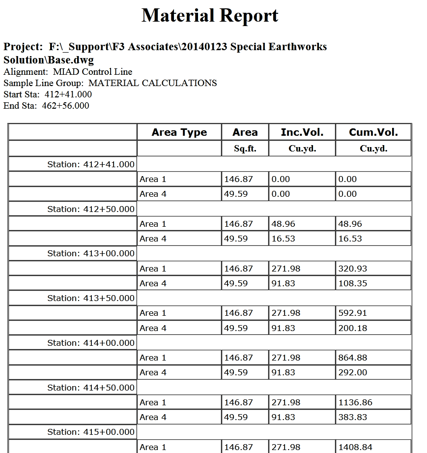
Press Ok again and you’re ready to calculate the volumes. In
the example, we are calculating Area 1 and Area 4 only.
While still on the Analyze tab, press the Volume Report
button. On the dialog, be sure to pick the style sheet called Select Material.
You will get a report similar to this: