Sunday, March 25, 2018

AutoCAD 2019 New Features


post by Timothy Corey


This post will describe the new features of AutoCAD 2019. A few of these features were introduced in AutoCAD 2018.1.2 Update.

Before we get started, here's my favorite new feature in AutoCAD 2019:


1. Refreshed Icons -- AutoCAD icons have been modified to have a more pleasing look and to be easier to see.


2. Drawing Compare -- This is a fabulous tool for anyone who needs to compare drawing revisions and wants to be able to quickly view, plot and report the differences. Here are two versions of the same drawing:


You might pick out one or two differences immediately, but how long will it take you to find twenty differences?

You will find DWG Compare on the on the Collaborate ribbon tab.


or on the Drawing Utilities sub-menu of the Application menu

Select the two drawing files you want to compare. If any drawings are open when you invoke the command, the current drawing will be auto-selected as DWG 1. The other drawing, DWG2, must be selected from browse, even if it is an open drawing.


Once the two drawings are selected, press Compare and watch the magic happen. Drawing Compare  will create a new drawing that looks similar to your two existing drawings, but there will be only a few colors.


If you have not modified the default colors, Green is for objects that are unique to DWG1, Red is objects unique to DWG2, and Grey is objects that are the same in each drawing. Orange is the color of the revision clouds that automatically encompass the differences.

Use Draw Order to set which comparison drawing display on top.


Turn on or off objects belonging to only one drawing or those objects that are common, and change colors for each:


Turn on or off the comparison results for Text or Hatch objects:


Turn the Revision Clouds on or off, set the shape of the Revision Clouds, and set Margin between the cloud and the objects it encompasses. A smaller margin value will produce more and smaller revision clouds:


Small Margin setting:


Larger Margin setting:

Notice as you slide the margin that the Total Number of Change Sets updates to show the number of revision clouds.

Use the arrows to let AutoCAD zoom you around the drawing, so that you can inspect and repair as necessary.

We don't know how, or if, this function will be implemented in Civil 3D 2019. Stay tuned...

3. AutoCAD's Shared Views provide a fast and easy way for you to share design information without sharing your drawing files and without producing PDFs.

On the ribbon, go to the Collaborate tab, then Shared Views.


Press New Shared View. 


Give your share a name and decide which views to share. If you are currently working with Model tab open, selecting Share current view only, will include all model views, but not layouts. If a Layout tab is current when start the new share, and you select Share current view only, that layout will become the single sheet in your online share.


If you want your colleagues to be able to select objects and see their properties -- Layer, Color, Linetype, etc. -- be sure to turn on the option to Share object properties.

Once you press Share, and then press Proceed, the process will begin to run in the background. You can continue using AutoCAD as normally. You will be notified when your share is available for viewing.


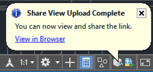
Press the View in Browser link and you will be taken to the Autodesk Viewer website with your model views and sheets listed on the left and displayed on the right.


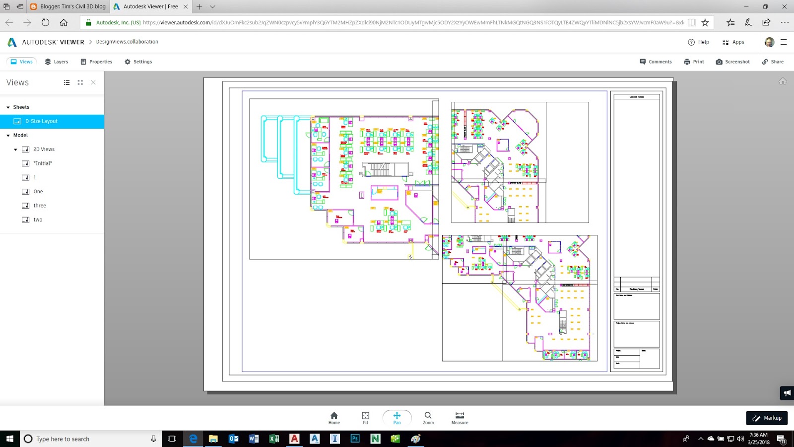
To share with others, simply enable the Share menu:


Expand  and set Sharing Options. When your settings are correct, press Copy to copy the link to the Clipboard. Paste the link into an email to send to those with whom you want to share.


Colleagues with whom you share will be able to comment and provide Markups.


4. We're very happy to see the new ability to Insert Named Views as Viewports. Once you've created your model views and you're ready to assemble them on sheets, use the Insert View command from the Layout ribbon tab.


While inserting, right click to view the drawing's scale list. Pick one and note the change in the size of the viewport. If you like the fit, move it into place and pick.


This new functionality lets you make rapid work of assembling sheets. Congratulations on your newly-found free time. Smiley wink.


As you can see from above, using Named Views is taking on a greater importance. Knowing that you will be creating more views, the software team have streamlined the dialog box where you create Views. A couple of clicks and you're done.


If you do want to see the full dialog, just press that little downward arrow in the bottom left corner.

You can streamline the process further, by Inserting a new view as a viewport. If you don't need to save the model view with a name, use the New View button from the Insert View gallery. This will let you pick a window for a new view, right click to set scale, and then pick a location with this single command. It's very efficient.


Here's a hidden gem of a feature, one I think many of our customers will find extremely useful. Once any viewport has been placed, select it and notice the triangular grip at its centroid.


Select the grip and you will be given a menu of scales. Pick a different scale and notice your viewport change size to accommodate the view at that scale.


Those are my favorite enhancement in AutoCAD 2019. Some others include better tools for identifying layer properties overrides in viewports and Xrefs, speed enhancements, and better support for 4k monitors.

Tim Corey


Tuesday, February 20, 2018

Modify the Toolbox Reports in Civil 3D

Autodesk Authorized Reseller since 1989. Redding, CA.

Here's a solution to a problem we often encounter: The ability to modify the reports that are presented to us by the Civil 3D Toolbox.

Let's say we have a Pipe Network and we want to create a Pipe report. The standard version of this report includes both center-to-center and edge-to-edge distances.


We don't want that. We want only center-to-center in our report. How do we do that?

How to eliminate the text "edge-to-edge" from the report's column heading.

Make a copy of your existing "Pipes Only.xsl" file, typically found in C:\ProgramData\Autodesk\C3D 2018\enu\Data\Reports\xsl


Open the xsl file with Notepad.


Find (Ctrl + F) the text: 
edge-to-edge


Delete the line from the file. The effect is that the  text from the column heading will be eliminated. In the case above, the text is being removed from the report if the display unit is foot and the length type is 2D. If you want to eliminate the text from all reports, including metric and 3D, continue searching for that string and deleting until there are no more. Save the file but do not close Notepad.

How to eliminate the edge-to-edge value from the data field.

If you were to perform only the step described above, you would get rid of the text from the report heading, but the edge to edge value would still be displayed in the data fields of the report.

Go back to the top of the file, click your cursor, and now search for string(landUtils:CC2EE


Eliminate or comment out the entire line. To comment the line out, inside the < bracket, type !--. At the right end of the line inside the > bracket, type: --


Using this technique, delete, or comment-out, the two lines indicated by arrows, above. This will eliminate the edge to edge distance. Do the same step in the 3D length type section. Save the file and exit Notepad.

Go back to Civil 3D and run the report again.


 What if you want to keep the original report style, but make a new style that will also be available on the Toolbox?

Close Civil 3D for this step.

Don't use the process above on the Pipes Only.xsl file. Make a copy, name it appropriately. We will use Pipes Only cen-to-cen.xsl for our example. Make the changes above in the new file.

Now, browse to C:\ProgramData\Autodesk\C3D 2018\enu\Data\ToolBox and locate the file called ToolBoxCfg.xml. 

Edit that file using Notepad. Search for Category name="Pipes"


Copy and Paste one the line with You will have duplicate lines:


Now, change the tool name to one of your choosing. Scroll along the same line and find where it specifies the execute file. Put in the correct name of your modified xsl file.


Save and close the file.

Open Civil 3D. On the Toolbox tab, find your Pipes report area. If you don't see your new report style, right click on the Pipes heading and Refresh.


Thursday, June 15, 2017

How to change precision of scale factor for ground to grid conversion

This short post is important for those of you who are land surveyors. If you need to display ground to grid scale factor for points, but need more than the three decimal place precision that is standard "out of the box", then read on.


We want eight decimal places for our example. To set that, go to the Settings tab of the Toolspace, right click the drawing name, pick Edit Drawing Settings.


Go to the Ambient Settings tab, find and expand Unitless, and set your precision:


Now your scale factor will display correctly:


Monday, May 8, 2017

A dynamic block that reads tree trunk and drip diameters from Civil 3D COGO Points


A dynamic block that reads tree trunk and drip diameters from Civil 3D COGO Points


This blog is being written while I develop a workflow that allows a land surveyor to import points, having different values for trunk and drip diameters, and have AutoCAD insert a dynamic block whose trunk and drip lines can be scaled independently of one another. This workflow will rely on AutoLISP programming to automate the insertion and scaling of the blocks, based on the values obtained from the points.

Create the dynamic block

I will start by creating the dynamic block. My block has simple objects, a circle and a hexagon,but you can dress yours up. The diameter is 1. This is important. Also, notice the center of the circle is at 0,0, the block's insertion and scale point.


I created a Linear Parameter for Drip and another for Trunk. I used quadrants of the circle as the snapped control points for both Parameters.

Then I added a Scale Action to each Parameter. I changed the properties of the Actions, changing the base type to Independent and being sure Base X and Base Y are both set to 0.


The point description 

For this workflow, I am going to use point raw description in the same way as Description Keys. The LISP routine is going to expect "TREE 12 36" in the description field to represent a tree with 12 inch trunk and 36 foot drip.

If you prefer to use User Defined Properties for Points (UDP), that is certainly a legitimate way of doing this.Your LISP will be different than mine.

The trunks have been input in inches, and my LISP routine will account for this. Here's what my descriptions look like:


Let's import the points and then we can get to programming, the fun part of all this.


Using LISP to marry the dynamic blocks to the COGO Points


So we have the points, and the descriptions are correct. Now we write the program that will marry the dynamic blocks to the points. 


(vl-load-com)

(defun c:go ( / pts len ctr pt obnam desc)
  (prompt "Select Points: ")
  (setq pts (ssget)
len (sslength pts)
ctr 0
  )

  (while (< ctr len)
    (setq pt (vlax-ename->vla-object (ssname pts ctr))
 obnam (vlax-get pt 'ObjectName)
    )
    (if (= obnam "AeccDbCogoPoint")
      (progn
(setq desc (vlax-get pt 'RawDescription))
(if (= (strcase (substr desc 1 4)) "TREE")
 (progn
(GetTrunk desc)
(InsBlock trunk drip)
))
      )
    )
    (setq ctr (1+ ctr))
  )

) ;end defun c:go


(defun GetTrunk (str / len txstr len stpt space1 space2)  
    (setq space1 (vl-string-position (ascii " ") str 0))
    (setq trunk (substr str (+ 2 space1) 2))
    (setq drip (substr str (+ space1 5) 2))
   (princ)
);end defun


;function to insert the block

(defun InsBlock (trunk drip / trunk drip)
  (setq pt-ins (list (vlax-get pt 'Easting)
    (vlax-get pt 'Northing)
    )
)
  (vl-cmdf "insert" "tree" pt-ins "1" "1" "0")
  (setq ob (entlast))
  (TreeSizer ob trunk drip)
  )
;next step is to modify the two parameters using the trunk and drip.


;--------------------function to modify block parameters to scale for trunk and drip
  
(defun TreeSizer (blk trunk drip / blkv dynprops trunksize dripsize)
  (setq blkv (vlax-ename->vla-object blk))
  (setq DynProps (vlax-invoke blkv 'GetDynamicBlockProperties))
  (setq Trunksize (nth 2 dynprops))

  (setq Dripsize (nth 0 dynprops))
  
  
  (vlax-put-property
    Trunksize
    'Value
    (vlax-make-variant (* (atof trunk) 0.08333333) vlax-vbDouble) ;this applies ft to inch scale factor
    )
  (vlax-put-property
    Dripsize
    'Value
    (vlax-make-variant drip vlax-vbDouble)
    )
) ;end defun

I use c:go so I can start the program by typing Go at the command line. Replace the word Go with what you want to type to make it run.

The main routine calls a couple of functions: GetTrunk takes the point description and separates the trunk diameter from the drip diameter TreeSizer accepts block name, trunk size and drip size and then modifies the dynamic block properties accordingly. InsBlock is used to insert and then modify the block.

Run it and you get this:


This is a proof of concept. The LISP can be modified to accommodate other tree types, so if you separate out by Oak, Pine, etc., it would be easy to make this work for you. If you need help, call me in California: 530.221.2994


Monday, April 17, 2017

New features in AutoCAD Civil 3D 2018


by Timothy Corey

This article will explain new features of AutoCAD Civil 3D 2018.

1. The AutoCAD .dwg file format has been updated and can no longer be directly opened by previous versions of AutoCAD. This applies to all flavors of AutoCAD: AutoCAD, AutoCAD Architecture, AutoCAD Civil 3D, AutoCAD Map 3D, etc.


2. Offset Alignments with Dynamic Profiles -- Now when you create an Offset Alignment, you can have Civil 3D automatically create a profile for that alignment. The new profile gets its elevations by your setting of the cross slope from the main profile. The new profile can be placed in the existing profile view as a superimposed profile. 


Notice how you can set a profile view into which you superimpose the new offset profile and how you can set a cross-slope.


If you need finer control of the cross slope, say you want to slope at -4% within a particular station range, after the offset alignment and profile have been created, click the offset alignment and on the Ribbon, find Offset Profile Properties.


On the Offset Parameters tab, create Cross Slope Regions. Notice how you define the transition between cross slope regions. In the example below, the cross slope will transition from -2% to -4% over 200' of profile, will be at -4% for 300', and will transition back to -2% over 200'.


All that, and it's dynamic. If you modify the main profile, the offset profile will update.


3. Create Connected Alignment -- This feature allows to you create an alignment and profile that "snap" to two other alignment and profile pairs. Think snap-able curb returns.

First, Create Connected Alignment.


You will be prompted to select the two alignments that will control your new alignment. Once you do that, you are prompted to "Pick a location for the selected alignment." Select a point that represents which curb return to create. In a T intersection, there will be two possibilities and in a crossing intersection, there will be four. 


Note the connection alignments, set the curve radius and the connection overlap. This places a small segment directly atop the connection alignment on each end of the return. The overlap cannot be 0.


Move to the Connected Profile tab and set your profile options:


4. Create Corridor with Multiple Baselines. Used in conjunction with Offset Alignments and Dynamic Offset Profiles, this feature removes the need for Offset Assemblies. Previously, you would use an Offset Assembly in areas where you wanted to control the corridor from a main baseline, but you wanted some subassemblies to be perpendicular to a different alignment. A good example is where you have a bus turnout and you want the curb/gutter/sidewalk to transition, but have the subassemblies perpendicular to the new curb line, not centerline.


This new features allows you to reduce the complexity of Assemblies and to set different frequencies. Because the offset alignment and its dynamic profile are tied to the centerline and the lane subassembly transitions are tied to the offset alignment and profile, the entire corridor is easily controlled by modifying one baseline. 

Having different frequencies does cause a small issue with the surfaces you create from your corridor. If you use subassembly links, like Top, to create the surface, you might get some undesirable results:


We get better results using feature lines as the data type when we create corridor surfaces.


5. Relative Elevation Feature Lines -- Relative to what? Relative to a surface! That's right, when you create or edit a feature line, you can tell all or some of its elevation points to be relative to an existing surface. Want the base of the retaining wall 12 inches below the FG surface? No problem.

When you create a feature line, at the point where you tell it which surface to use for its elevation source, you'll have the option to set the elevation relative to the surface.


A nice new detail: After setting the first point as relative to a surface, when you are ready to input the elevation for a subsequent point, the command line defaults to Relative Elevation with the same relative value you used for the previous point. No more saying SU for every single point you want to place on a surface.


As the surface is modified, all feature line points that are derived from the surface relationship will update. 

6. Corridor overlap resolution -- In areas where your subassemly links overlap one another, your corridor will suffer from what are commonly called "Bowties".


Well, now Civil 3D will either clean this up for you or let you clean it up using the new Bowtie Cleanup Tools.

To use the automatic tool, be sure you set corridor feature settings to allow cleanup for your geometry type:


Set the Automatic Clear Bowtie Options.


To use the manual tool, pick the corridor in the drawing window. On the ribbon, find Clear Corridor Bowties.


Delight in your results


7. Some of the tools that had been introduced as subscription extensions in previous versions, such as Pipe Sizing and Analysis, Traverse Editor and Plan/Plan Sheet Production have been enhanced and have graduated to become "included" commands in AutoCAD Civil 3D 2018. Congratulations to those commands.

Best regards,

Tim