using AutoCAD Civil 3D
Civil 3d 2009 has a new feature that allows you to turn on a line display in section view. If you edit your alignment style, look on the Display tab and set the View Direction to Section. Turn on Line Marker in Section. This will draw a line representing your alignment in any section view it crosses.
This is nice, but what if you want to shorten the line and label it with some text, like ROW? Follow these instructions:
Create the necessary styles to represent the ROW the way you want it presented
in Section view. The ROW label will be represented using a Point code defined
inside a code set style.
in Section view. The ROW label will be represented using a Point code defined
inside a code set style.

The software doesn’t ask for a new point code name, but makes one called NEW CODE. You can rename it from the list by selecting in the name box. I called mine ROW.
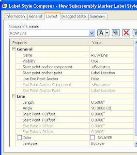
Next, create a new label style for the Point code you called ROW. Delete any components that might be in the dialog, and then add a line component. Set it to the length you want and an angle of 90. Scroll to the top of the Code Set Styles dialog and add a new Link code. Give it a style of _No display (you might have to create it) and rename the code from New Code to ROW. Exit the Code Set Styles dialog. That’s the end of step 1.
This exercise assumes you have already created a typical assembly. If you have not, do so now. Once you have a completed assembly object, follow these instructions to add the ROW subassembly.
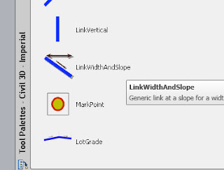
Add a ‘Link Width and Slope’ subassembly (it’s on the Imperial Generic tab) to each side of the Assembly.
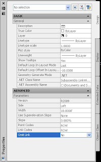
In the Properties dialog, the width you set doesn’t matter if you are going to make the ROW point transition to follow a meandering Right of Way. If the Right of Way is parallel to your centerline, set the correct value here.
You might consider using a 0% slope so the ROW point displays at the same relative elevation in each cross section.
Replace the Point Codes and Link Codes with the new ones you made in the Code Set Style. I called both of mine ROW.
You can optionally skip the step of creating a new Link Code and simply change Omit Link to Yes.
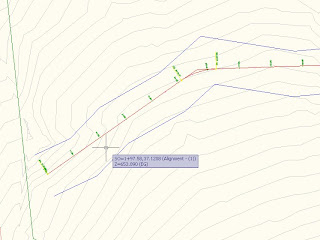
With Civil 3D 2009, you can delineate your Right of Way using Polylines, Alignments, or Feature Lines. In 2008 and earlier version, you must create Alignments.
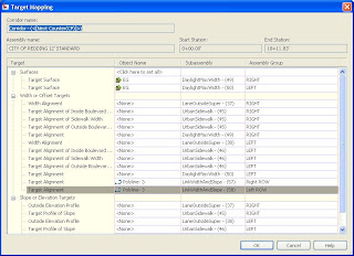
When you set your targets in the corridor properties, you’ll see that the two Link Width and Slope subassemblies need Target Alignments. Attach the transition objects you delineated previously. I my case, I am attaching to the two polylines that represent my ROW.
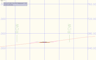
When you view/edit corridor sections, or use the corridor as a data source in cross sections, the ROW will display with your lines and labels per your ROW point code label style.


No comments:
Post a Comment