Sunday, January 18, 2015

Creating AutoCAD Solids from Civil 3D Surfaces and Pipe Networks


Submitted by by Timothy Corey


The last item in our exploration of Civil 3D 2015 Productivity Pack 1 is the tool for creating AutoCAD Solids from Civil 3D Surface and Pipe Networks.
 
Why would you want to do this? One good reason is that AutoCAD Solids can be passed on to non-Civil 3D users who need to create 3d models and/or renderings of projects. If an architect wants your surface so he can create a visual, give him a solid of the surface. These solids can even be exported to a 3D printer for use in a physical model.
 
We are going to start our example with an existing ground surface and the outline of a baseball diamond. The architect wants the original ground and the design surfaces as separate objects. The OG needs to have a masked area where the FG fits in.
 
Here's our starting point, an OG Surface and a surface that is part of a Grading Group.


First thing I want to do is create a hole in the OG so that no part of FG will be obscured. I don't really want to edit the OG, so I create a new surface and paste OG into that.


Now, add a Hide Boundary, using the baseball field surface as its definition.


On the Command line, you will be prompted to select object or Surface. Opt for Surface and select the ball field surface when prompted.


Now we're ready to create solids.
 
On the Toolbox tab of Toolspace, expand Subscription Extension Manager,  expand Civil 3D Productivity Pack 1, expand Create AutoCAD Solids, right-click Create 3D Solid from Surface, select Execute...


On the dialog, select the surface being extracted to solid.
 
Set your Vertical definition. Depth will give a thickness that is based on the surface point to which each point on the solid is related. At fixed Elevation will give you an even base. If you want your surface to sit on a table top (virtually or 3d-printed) use this option. If you want your solid surface to intersect with another surface, use At a surface. Our example uses At fixed Elevation.
 
Set Drawing Output settings. The solid can either be added to the current drawing or to a new drawing and can have Layer and Color preset.


Once we press Create Solid and wait a while (complex surfaces can take a long time to process,) we get a 3D solid of our surface. Notice the hole where the FG will fit.


Do the same for the FG:
 

These solids can be used in a number of Autodesk (and competitors') products, including Revit, 3DS Max Design, NavisWorks and InfraWorks.


Thursday, January 8, 2015

More information on Productivity Pack 1 -- COGO Editor


submitted by Timothy Corey


This post will cover features of the new Coordinate Geometry Editor (heretofore called COGO Ed in this blog) that has been introduced as part of AutoCAD Civil 3D 2015 Productivity Pack 1.


In this example, we will create a traverse using points imported from a field survey. They exist in the drawing file as Civil 3D COGO Point objects. Notice two points near the start of the traverse. The first is the start point, the second is the point calculated from the final shot back to the point of beginning. In this exaggerated example, you can easily see the traverse error. This point will be compared to the point of beginning in order to calculate and report the traverse error.


To open COGO Ed, navigate to the Toolbox tab of the Toolspace, expand Subscription Extension Manager, expand Civil 3D Productivity Pack 1, expand Coordinate Geometry Editor, right-click Launch Coordinate Geometry Editor and select Execute...


COGO Editor appears on your screen, below the Command prompt, pushing the Command prompt upwards, obscuring part of your drawing area. You can drag the interface out of this position (and onto a different monitor if you have one) if you prefer.


If the screen is blank, like above, you can start inputting traverse sides. If there is previous data, start a new traverse by selecting the New button in the upper left.
 
 
In the input area, be sure the first Side is set to Point. Click in the Location column and type the point number of the POB, 1 in the example. If you don't know the point number, pick the little arrow that shows up in the Location box and then pick the point object on the drawing screen. A further option allows you to press X (for Xyz) to use an osnap to snap to a point or other object. Maybe the traverse is represented by lines and you want to snap to an endpoint.


The second row of input will now set Line as the Side type. Leave that as shown. Click in the Location column for this row and type the first foresight number, 2 in our example. The bearing and distance from 1 to 2 display in COGO Ed and along a temporary graphic in the drawing.


Continue inputting point numbers (or picking points/locations) around the traverse. Pick your final foresight point just like all the others. Stop your input entry after entering the final foresight point.


Now, to check our closure. Pick the Balance tab at the side of the dialog. Double click in the Control Point column of the row entitled Totals. Type the point number of your POB/Closure Point. In our example, that's point 1. Your closure will appear at the bottom of the dialog.


Lastly, you can view the results of various traverse adjustments by selecting your adjustment type in the dropdown at the top of the dialog. In the example, we run the Crandall Rule method.


The example above uses existing points, but let's say you have bearings and distances for your input and you don't want to create points. You can input the field data directly into the dialog. You can mix points with field input and locations selected on the screen. You can even load a traverse from an existing polyline and run an adjustment on that.
 
A traverse can be saved and recalled by pressing the Save button on the Entry tab.
 
Once complete, you can have the traverse drawn as a polyline. Press the Create Polyline from Traverse button on the Entry tab.


That's all for now. A review of the Create AutoCAD 3D Solids tool is coming soon....


Tuesday, January 6, 2015

Civil 3D 2015 Productivity Pack 1 now available


Autodesk has released the new Productivity Pack 1 for AutoCAD Civil 3D 2015. This set of tools is available only to current members of Autodesk Maintenance Subscription or Desktop Subscription.

Autodesk® AutoCAD® Civil 3D® 2015 Productivity Pack 1 consists of the following features:
  1. Ability for AutoCAD Civil 3D users to directly read Autodesk InfraWorks models for detailed design / production tasks
  2. Coordinate Geometry Editor utility that provides a streamlined process for point, line, and curve entry and balance
  3. Automated process for creating AutoCAD 3D solids from Civil 3D surface models and pipe networks
The following post details the InfraWorks model import function. Later posts will cover the other two features of the Productivity Pack.

Directly Read InfraWorks project files

Start with an InfraWorks project:


Switch to Civil 3D. On the Toolspace, Toolbox tab, expand Subscription Extension Manager and expand Open InfraWorks Model. First, configure import settings by right-clicking on Configure InfraWorks - Civil 3D Exchange Settings.


Use the ellipsis buttons to the right on each row to access the style and layer settings for each InfraWorks/Civil 3D object type. For example, to set defaults for Surfaces, press the ellipsis to the right of the Terrain Surfaces / TIN Surfaces row.


Set the surface style and layer defaults and press OK.


Configure similar settings for other object types. Before you exit, be sure you save your settings to a settings file so you can recall them later. The import routine requires that you pick a settings file. Note: The default folder for these files is C:\ProgramData\Autodesk\C3D 2015\enu\Data\InfraWorks Object Settings\Imperial (or Metric.)


After pressing Save, and when finished with settings, press OK to exit the dialog.

Now right-click Open InfraWorks Model on the toolspace and Execute.


Select the InfraWorks Model using the folder button at the top. Once the model is selected, you will be shown the model's coordinate system information. If you need to convert to a different coordinate system, there is a button allowing you to Set a Coordinate System for your Civil 3D drawing. Either import the entire InfraWorks model area or set your own Area of Interest.

This very cool feature will automatically load AutoCAD's online mapping as a background to your drawing, zoomed in on the project area read from the InfraWorks file. You can then select a rectangular sub-area of the project. If you are not already logged in to Autodesk 360, you will be prompted. This is a requirement for this feature.


Be patient, it can take some moments for the map to load.

Pick the Object Settings file you created earlier.

If you would like to see and control which objects are to be imported (important, so you don't end up importing a hundred existing roads that are in InfraWorks for reference, but not needed for Civil 3D's detailed design) press Refine Selection Set. On large models, this can take quite a while, so don't reboot because you think the system is doing nothing. It's reading the model, but you aren't told progress. Just wait, or go get a cup of tea, stretch your legs, whatever.

When done setting the object import options, press Open Model.


Requirements: AutoCAD Civil 3D 2015 with Service Pack 2 installed. Autodesk InfraWorks 360 2015.3.

Thursday, November 13, 2014

How to disable Layout Tools Ribbon tab when switching to Layout


AutoCAD offers a set of tools available on a Contextual Ribbon Tab called Layout Tools. When you select a Layout (paperspace) tab below the drawing, the Layout Tools Ribbon Tab automatically turns on and becomes active. What if you don't like this behavior?


Rather than delete the tab from the CUI, let's make it so that it still becomes available, but AutoCAD does not switch to that tab automatically. Sounds like a good compromise, right?

Step 1: Open the CUI editor by typing CUI at the command line.


Step 2: In the upper left box, find and expand Partial Customization Files


Step 3: Find and expand ACAD, then find and expand Ribbon, and, finally, find and expand Contextual Tab States.


Step 4: Scroll down until you find Layout Tools. Expand that and click on Contextual Layout Tools.


Step 5: Look on the right side of the dialog, find and drop down the list that is titled Contextual Display Type. Change it to Full without Focus.


Step 6: Hit OK.
 
Now, when you move from the Model tab to a Layout tab, the Layout Tools Ribbon Tab will appear at the end of the Ribbon, but it will not be active. If you want to use it, click it, otherwise AutoCAD will remain on whichever tab was active when you moved to the Layout.


Tuesday, October 7, 2014

Corridor Intersection Primer -- Manually Create an Intersection


Although AutoCAD Civil 3D includes an Intersection object, making complex intersections easier to design and maintain, it is helpful to know how to manually create an intersection so you have a better idea what the Intersection Wizard is doing in the background.
This article takes you through a very simple example of how to manually create an intersection using an AutoCAD Civil 3D corridor.
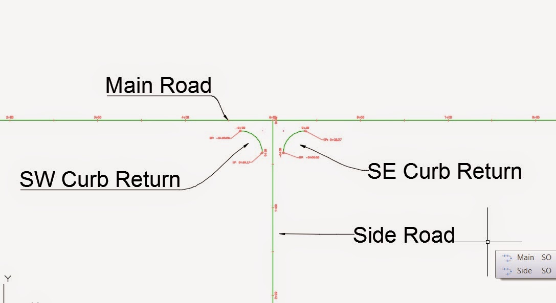
It helps me to layout the intersection using lines or polylines. In this example, we have a main (through) road and a side road that create a T intersection. Each of these will become an alignment. In order to properly model the intersection, we will also need an alignment representing each curb return.

The first step is to layout the alignments using lines and arcs.


Next, use CreateAlignmentEntities command to create an alignment from each object. We end up with four alignments.

You will need to create a finished ground (layout) profile for each alignment. You do not necessarily need existing ground, but in most cases you will use it for reference. Here we have design profiles for Main Road, Side Road, SW Curb Return and SE Curb Return.


Next, create your Assemblies. In the example, Main Road and Side Road will use the same full-width assembly, which includes 12' travel lanes and Curb/Gutter subassemblies on each side. For simplicity, we are not using shoulders or daylighting.

Notice above that we have a full-width Assembly for Main and Side, but we also have a half-width Assembly that will be applied to Main within the region between the curb returns. Also notice that the Curb Return Assembly includes a lane on the left side and a curb/gutter on the right. This is so that we can make the lane widen and elevate to follow the centerlines of Main Road and Side Road.

The next step is to create the corridor. This is the rough-draft version and will include the full-width Assembly running the entire length of Main Road.


For our example, lets not create additional regions yet and view the corridor at this point.


This looks pretty good, but we now need to eliminate the travel lane and curb-gutter from the intersection. We do this by creating a region that uses the half-width assembly. Go into Corridor Properties, Parameters tab, right click on the existing region and select Insert Region After.


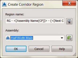
When the Create Corridor Region dialog appears, select your Half Width Assembly and press OK.


The baseline Main will now include two regions. You must adjust their stationing. In the first region, we will leave the starting station at 0+00, but we want the end of this region to be the station where the SW Curb Return begins. Press the button at the right side of the box for End Station in the first region.


After a pause, the program will take you to the drawing screen, where you can snap to the endpoint at the beginning of the SW Curb Return alignment. Use the same point as the start station for the next region and use the far end of the SE Curb Return alignment as the end of the second region. Right click the second region and pick Insert Region - After, choosing the Full Width assembly for this last region on the Main baseline. Your corridor properties should look similar to this:


Notice the baseline name followed by its three regions. Press OK and you will have a corridor that look like the following. Notice the gap in the intersection.


The next step is to add a baseline for the Side Road alignment. Go back to Corridor Properties, Parameters tab. Press the Add Baseline button.


On the Create Corridor Baseline dialog, pick the Side road in the Horizontal Alignment dropdown list.


In the Profile column for the Side Road baseline, click where it says Click Here. Select your finished ground profile.


A region will not automatically be created, so right click the Side Road baseline and select Add Region.


On the dialog, pick the Full Width assembly. Pick the + sign next to the Side Road baseline to expose the new region. Set its start station to the southerly end of the SW Curb Return alignment. Press Ok. Now you have a single corridor with two baselines and a gap in the intersection area.


Using the same method as before, add each curb return alignment as a baseline, picking the FG profile and creating a region that uses the Curb Return assembly. The region start and end stations will be left to the defaults, but, for each curb return baseline, we need to set targets. For the first baseline, press the Target ellipsis button. Notice that the LaneSuperElevationAOR is asking for a Width Alignment and an Outside Elevation Profile.


Press where it says None in the Width Alignment row and Object Name column. Set Object type to target to Alignments. In the Select Alignments box, hold CTRL  while selecting Main and Side alignments. Press Add and then OK.


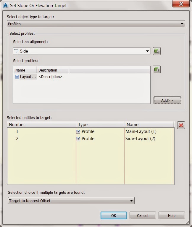
Now press None in the Outside Elevation Target row and Object Name column to select the elevation control. Set Object type to target  to Profile. Select Main alignment and its finished ground profile and press Add. Then select the Side Road alignment and its finished ground profile and press Add.


Press Ok until you are back at the Parameters tab. Perform the same method to set the targets for SE Curb Return baseline. Finally, press OK to get out of Corridor Properties and check out your intersection.