Thursday, November 13, 2014

How to disable Layout Tools Ribbon tab when switching to Layout


AutoCAD offers a set of tools available on a Contextual Ribbon Tab called Layout Tools. When you select a Layout (paperspace) tab below the drawing, the Layout Tools Ribbon Tab automatically turns on and becomes active. What if you don't like this behavior?


Rather than delete the tab from the CUI, let's make it so that it still becomes available, but AutoCAD does not switch to that tab automatically. Sounds like a good compromise, right?

Step 1: Open the CUI editor by typing CUI at the command line.


Step 2: In the upper left box, find and expand Partial Customization Files


Step 3: Find and expand ACAD, then find and expand Ribbon, and, finally, find and expand Contextual Tab States.


Step 4: Scroll down until you find Layout Tools. Expand that and click on Contextual Layout Tools.


Step 5: Look on the right side of the dialog, find and drop down the list that is titled Contextual Display Type. Change it to Full without Focus.


Step 6: Hit OK.
 
Now, when you move from the Model tab to a Layout tab, the Layout Tools Ribbon Tab will appear at the end of the Ribbon, but it will not be active. If you want to use it, click it, otherwise AutoCAD will remain on whichever tab was active when you moved to the Layout.


Tuesday, October 7, 2014

Corridor Intersection Primer -- Manually Create an Intersection


Although AutoCAD Civil 3D includes an Intersection object, making complex intersections easier to design and maintain, it is helpful to know how to manually create an intersection so you have a better idea what the Intersection Wizard is doing in the background.
This article takes you through a very simple example of how to manually create an intersection using an AutoCAD Civil 3D corridor.
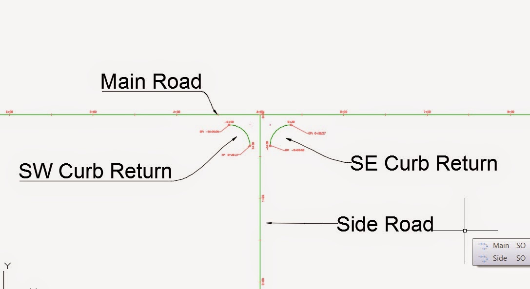
It helps me to layout the intersection using lines or polylines. In this example, we have a main (through) road and a side road that create a T intersection. Each of these will become an alignment. In order to properly model the intersection, we will also need an alignment representing each curb return.
The first step is to layout the alignments using lines and arcs.


Next, use CreateAlignmentEntities command to create an alignment from each object. We end up with four alignments.

You will need to create a finished ground (layout) profile for each alignment. You do not necessarily need existing ground, but in most cases you will use it for reference. Here we have design profiles for Main Road, Side Road, SW Curb Return and SE Curb Return.


Next, create your Assemblies. In the example, Main Road and Side Road will use the same full-width assembly, which includes 12' travel lanes and Curb/Gutter subassemblies on each side. For simplicity, we are not using shoulders or daylighting.

Notice above that we have a full-width Assembly for Main and Side, but we also have a half-width Assembly that will be applied to Main within the region between the curb returns. Also notice that the Curb Return Assembly includes a lane on the left side and a curb/gutter on the right. This is so that we can make the lane widen and elevate to follow the centerlines of Main Road and Side Road.

The next step is to create the corridor. This is the rough-draft version and will include the full-width Assembly running the entire length of Main Road.


For our example, lets not create additional regions yet and view the corridor at this point.


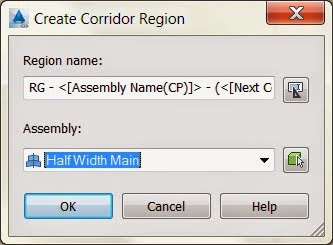
This looks pretty good, but we now need to eliminate the travel lane and curb-gutter from the intersection. We do this by creating a region that uses the half-width assembly. Go into Corridor Properties, Parameters tab, right click on the existing region and select Insert Region After.


When the Create Corridor Region dialog appears, select your Half Width Assembly and press OK.


The baseline Main will now include two regions. You must adjust their stationing. In the first region, we will leave the starting station at 0+00, but we want the end of this region to be the station where the SW Curb Return begins. Press the button at the right side of the box for End Station in the first region.


After a pause, the program will take you to the drawing screen, where you can snap to the endpoint at the beginning of the SW Curb Return alignment. Use the same point as the start station for the next region and use the far end of the SE Curb Return alignment as the end of the second region. Right click the second region and pick Insert Region - After, choosing the Full Width assembly for this last region on the Main baseline. Your corridor properties should look similar to this:


Notice the baseline name followed by its three regions. Press OK and you will have a corridor that look like the following. Notice the gap in the intersection.


The next step is to add a baseline for the Side Road alignment. Go back to Corridor Properties, Parameters tab. Press the Add Baseline button.


On the Create Corridor Baseline dialog, pick the Side road in the Horizontal Alignment dropdown list.


In the Profile column for the Side Road baseline, click where it says Click Here. Select your finished ground profile.


A region will not automatically be created, so right click the Side Road baseline and select Add Region.


On the dialog, pick the Full Width assembly. Pick the + sign next to the Side Road baseline to expose the new region. Set its start station to the southerly end of the SW Curb Return alignment. Press Ok. Now you have a single corridor with two baselines and a gap in the intersection area.


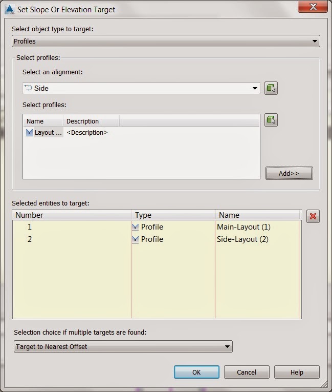
Using the same method as before, add each curb return alignment as a baseline, picking the FG profile and creating a region that uses the Curb Return assembly. The region start and end stations will be left to the defaults, but, for each curb return baseline, we need to set targets. For the first baseline, press the Target ellipsis button. Notice that the LaneSuperElevationAOR is asking for a Width Alignment and an Outside Elevation Profile.


Press where it says None in the Width Alignment row and Object Name column. Set Object type to target to Alignments. In the Select Alignments box, hold CTRL  while selecting Main and Side alignments. Press Add and then OK.


Now press None in the Outside Elevation Target row and Object Name column to select the elevation control. Set Object type to target  to Profile. Select Main alignment and its finished ground profile and press Add. Then select the Side Road alignment and its finished ground profile and press Add.


Press Ok until you are back at the Parameters tab. Perform the same method to set the targets for SE Curb Return baseline. Finally, press OK to get out of Corridor Properties and check out your intersection.


Wednesday, September 17, 2014

How to create a fence style in Autodesk InfraWorks


We are often asked how to create a fence style in Autodesk InfraWorks, using a 3d model from SketchUp, AutoCAD, 3DS Max, Design or some other modeling program.

The following is a workflow you can follow in order to accomplish this task. We use AutoCAD to create and export a 3D model of the fence components.

Starting in AutoCAD (or AutoCAD Civil 3D) draw a 3d object that represents a fence board or section.

If you work in meters, do so. If you work in feet, be advised that InfraWorks is going to read the units of your 3D model in meters. If you want to be able to apply model scales that represent feet, create your model in AutoCAD and then scale times 0.3048 before exporting to FBX format.

We first draw our fence section design using standard AutoCAD objects. If you use Front View (and UCS to match,) the X, Y and Z will match InfraWorks.


Next, use the PressPull command to make an extrusion of the thickness of the fence. Optionally, add a material.
 
You should have a 3D object:
 
 
Use the AutoCAD FBXExport command to export the 3D object to an fbx file. This format is compatible with InfraWorks.


On the FBX Export Options dialog, set the pulldown to Selected Entities and then press the button to Select Objects:


We're not exporting lights and cameras, but be sure Objects is checked and Materials if you applied one or more.

Open your project in InfraWorks and turn on the Style Palette. Browse to any collection within the 3D Model tab. Remember where you are, you'll need to get back here later. Press the green plus sign at the bottom of the Style Palette and you'll get the Define New 3D Model dialog:

 
Press the ellipsis button at the top right to browse to the location of the FBX file you exported. If, in AutoCAD, you created the model to the exact size you want, in meters, you can leave the scaling alone. If you need to adjust scaling, do that on the dialog. Note the X, Y and Z scales.
 
Finish with your settings and press OK. You will be placed back on the Style Palette, there will be a new style and the style name will be in edit mode. Type the name you want to apply to this new 3D model style.
 
 
Move back to Civil 3D and use the MapExport command to export the polylines that represent the fenceline. Use either SDF or SHP format.
 
 
Using Windows Explorer, drag and drop the newly created SDF or SHP file onto InfraWorks. On the Data Source Configuration dialog, set Type to Barriers. In the Rule Style box, press the button for Style Chooser (the pencil). Change the tab to 3D Model, browse through the categories and find the new 3D Model style you created in the previous step.
 
Press OK.
 
Back on the Data Source Configuration dialog, if you want the fence to follow your terrain, go to the Source tab and set Draping Options to Drape.
 
Move to the Table tab, set your Object Spacing. In our example, the fence board is 1' wide and we want no gap between boards, so we set Object Spacing to 1. Press the Close and Refresh button. Your fence displays:
 

Friday, February 7, 2014

How to set a Civil 3D alignment to measure curves by chord


by Timothy Corey

Today's issue has to do with the way Civil 3D measures and reports curves lengths. In most instances engineers want lengths reported along the arc, but in certain cases, especially when working with railroad alignments, the engineer wants lengths input and reported along the chord. 

Here's how to set that up:

If you are creating a new alignment, on the Create Alignment - Layout dialog, just below where you input the alignment name, note the Type dropdown. If you drop this list down, pick the Rail alignment type. Next, create your alignment as you normally would.


After creating the alignment, select the alignment and go to Alignment Properties. Activate the Station Control tab. Because you set the alignment type to Rail, on the Station Control tab, you will have an option to Measure curves along chords.


If you have an existing alignment whose type is set to Centerline, go the the Information tab of Alignment Properties to change the alignment type to Rail and then go the the Station Control tab to turn on the option as shown above.


Wednesday, January 29, 2014

An AutoCAD Civil 3D workflow for calculating multiple material volumes within varying embankment zones


Folsom Dam is planning new embankment zones atop existing embankment. The new embankment zones will be built from various material types. Each material needs to be quantified at horizontal strata that increase in variable increments. The illustration below demonstrates a typical cross section with the geometry simplified for brevity:
 

Our task is to calculate the volumes of Area1 through Area 6. In this example we are using elevation increments of 5’.

We will be creating several Surface objects in order to calculate all of the volume options. We have named the surfaces in the diagram above.

Please note: For Surfaces A, B and C, we have used two links for each. The tops use LinkWidthandSlope and the sides use LinkSlopetoSurface. Be sure you use the same Link Code for the tops and sides of each material. For example, for Surface A, the top and side (in green above) have been assigned the same Link Code, A. This allows easy creation of a surface for that import material. 

The project specifications call for a vertical link to the existing embankment, but Civil 3D surfaces cannot handle vertical faces, so we used 10,000%. (Ten thousand percent, very near vertical)

This guide will not discuss how to create the basic elements of the design, objects like surfaces, alignments and corridors. It is assumed the reader already has these skills.

Create a corridor that models Existing Embankment and create a surface from that corridor. Here's the assembly we used in the example:


Assembly created for existing embankment. All links have the same code, "ExistingEmbankment."


Create a corridor and surfaces that model Surfaces A, B and C, targeting the existing embankment surface, which we created in the step above. We used a single corridor to model these three surfaces. Here's the assembly:


Green represents Surface A, blue for Surface B, orange for Surface C. Be sure to set Link Codes the same for links of the same surface and different than links for the other surfaces. We used codes A, B and C, but you can name them what you want. Capitalization matters. B and b are different codes.

VERY IMPORTANT NOTE: When you create these corridor surfaces, be sure to add boundaries that match the surface extents. In order for the process being described to work correctly, it is important that you do not skip this step. Each surface should have a boundary added. Just because the surface border looks right doesn't mean you don't need to add a boundary. It makes a big difference on how Civil 3D interprets the material outlines.

Up to this point, you should have four surfaces:


Create corridor and surface that models the surface Level 0. Rather than create three corridors and surfaces to make our three levels, in our example we created a single corridor and surface that modeled Level 0. We then created new surfaces for Level 5 and Level 10 and pasted Level 0 surface into those. Each was then raised the appropriate height. If you would rather use three corridors instead of the paste method, that's an entirely viable option.


The assembly for Level 0 consists of a single LinkWidthandSlope subassembly set at 0% and with an offset large enough to encompass all embankment zones. Be sure to use a unique Link Code such as LEVEL 0.


At this point, you should have three corridors and five surfaces:


Now you need to create the surfaces for Level 5 and Level 10 as described above. For each, create a new surface, Paste Level 0 and then raise the surface the appropriate distance.

Create your sample line group, including each of the surfaces as a data source.


In the example, we only use the surfaces and corridor surfaces as data sources, excluding the corridors objects.

Finally, it’s time to Compute Materials and create a volume report. 

From the Analyze tab of the Ribbon, select Compute Materials. In the upper left of the dialog, pick the button to create a new Quantity takeoff criterion:


You'll get this dialog:


Add a new material and rename it Area 1. Change the Quantity type to Fill. In the long/wide box labeled Define material, be sure Data type is set to Surface. Referring back to our original diagram, we can see that we need surfaces A, Level 5, Level 10 and Existing Embankment. Pick each and press the + button. These surfaces get added to the Material called Area 1. 

Note the condition column. Looking at the diagram:

You see that Area 1 is constrained by the various surfaces. Our fill zone is Below Surfaces A and Level 10 and Above surfaces Level 5 and Existing Embankment. Set your conditions accordingly.


If we were to continue and add Area 4 as an example, our fill area would be below surfaces B and Level 5 and would be above surface Level 0:


Once you have defined all the material areas, press OK. Back on the Compute Materials dialog, because we added actual surface names to the material definitions, you can press Map Objects with the Same Name button to fill the object names.


Press Ok again and you’re ready to calculate the volumes. In the example, we are calculating Area 1 and Area 4 only.

While still on the Analyze tab, press the Volume Report button. On the dialog, be sure to pick the style sheet called Select Material. You will get a report similar to this: