Thursday, December 18, 2008

Creating ROW label in section view
using AutoCAD Civil 3D

Civil 3d 2009 has a new feature that allows you to turn on a line display in section view. If you edit your alignment style, look on the Display tab and set the View Direction to Section. Turn on Line Marker in Section. This will draw a line representing your alignment in any section view it crosses.

This is nice, but what if you want to shorten the line and label it with some text, like ROW? Follow these instructions:


Create the necessary styles to represent the ROW the way you want it presented
in Section view. The ROW label will be represented using a Point code defined
inside a code set style.

Add a new Point Code.


For Marker Style, I use one that turns off the marker display in all view directions


The software doesn’t ask for a new point code name, but makes one called NEW CODE. You can rename it from the list by selecting in the name box. I called mine ROW.
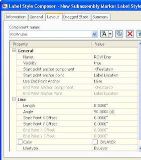


Next, create a new label style for the Point code you called ROW. Delete any components that might be in the dialog, and then add a line component. Set it to the length you want and an angle of 90. Scroll to the top of the Code Set Styles dialog and add a new Link code. Give it a style of _No display (you might have to create it) and rename the code from New Code to ROW. Exit the Code Set Styles dialog. That’s the end of step 1.


This exercise assumes you have already created a typical assembly. If you have not, do so now. Once you have a completed assembly object, follow these instructions to add the ROW subassembly.
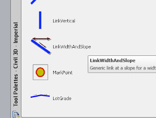


Add a ‘Link Width and Slope’ subassembly (it’s on the Imperial Generic tab) to each side of the Assembly.
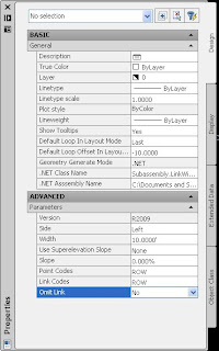


In the Properties dialog, the width you set doesn’t matter if you are going to make the ROW point transition to follow a meandering Right of Way. If the Right of Way is parallel to your centerline, set the correct value here.

You might consider using a 0% slope so the ROW point displays at the same relative elevation in each cross section.

Replace the Point Codes and Link Codes with the new ones you made in the Code Set Style. I called both of mine ROW.

You can optionally skip the step of creating a new Link Code and simply change Omit Link to Yes.
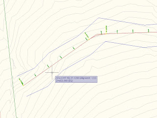


With Civil 3D 2009, you can delineate your Right of Way using Polylines, Alignments, or Feature Lines. In 2008 and earlier version, you must create Alignments.
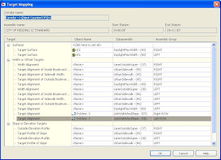


When you set your targets in the corridor properties, you’ll see that the two Link Width and Slope subassemblies need Target Alignments. Attach the transition objects you delineated previously. I my case, I am attaching to the two polylines that represent my ROW.
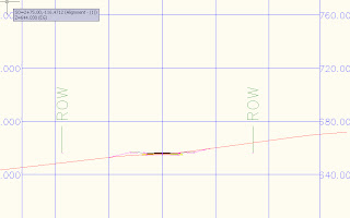


When you view/edit corridor sections, or use the corridor as a data source in cross sections, the ROW will display with your lines and labels per your ROW point code label style.




Saturday, November 22, 2008

Ground to Grid Coordinate Conversion

using AutoCAD Civil 3D


Why do I need to convert 'Ground' to 'Grid.'


When a surveyor goes to a site to take measurements, he might use a number of different methods to find 'North.' His north can be Magnetic North, True North, Grid North, or an assumed basis of bearing. Additionally, Grid data are converted for Earth's curvature, while Ground measurements are planar. If your survey data need to interface with georeferenced data -- often when you're interfacing to a GIS -- then you will need to convert from the Ground measurements to Grid data.

How to do Ground to Grid conversions with AutoCAD Civil 3D

Before you can apply the Ground to Grid conversion factors, you must assign a coordinate system to the drawing. Edit Drawing Settings and open the Units and Zone tab.


Under Categories, all US state plane categories will be found under USA, <>.

Available Coordinate Systems, make a selection. For example, Calif State Plane Zone 2, US Foot.


After setting the coordinate system, you can define your ground to grid conversion factors. Move to the Transformation tab.

Here you first turn on the dialog by putting a check next to Apply Tranform Settings and then enter your conversion factors.


When you go to import or exports points, notice the options to Do elevation adjustment if possible and Do coordinate transformation if possible. If you check these boxes, your data will be transformed to your assigned coordinate system using the factors you defined.


When you list points in Civil 3D, there are columns for Grid Northing and Grid Easting. These data columns can be also be accessed in the Point Editor, as content within Point Label Styles, and as point export columns.

Saturday, November 15, 2008

Reducing memory usage with Civil 3D

Using Civil 3D, memory management is very important. There are techniques you can utilize that will optimize your system resources by minimizing your memory use.

Indexing a reference drawing


Turn on Demand Loading using XREFCTL. Either set it to 1 or 2. 1 means that your Xref's are loaded and locked in their home path; 2 makes a copy of the Xref on your local workstation and that copy is loaded and locked, still allowing others to open and edit the Xref drawing.


INDEXCTL (stands for Index Control) is an AutoCAD command, used with the reference drawing open, that will index your drawing objects by layer and/or spatially. The advantage is that when you reference this drawing into another, objects that are on frozen layers will not be loaded into memory. Set INDEXCTL to 3 in the reference drawing to turn on both layer and spatial indexing.


XCLIP is the command you use, inside the container drawing, that will not only clip your Xref visually, but will also reduce its memory footprint by not loading those objects that lie outside the XCLIP boundary. To utilize layer indexing, simply freeze Xref layers in the container drawing. Be sure you leave VISRETAIN set to 1.


Civil 3D Surface Data Clip Boundaries


To reduce the memory footprint of a Civil 3d Surface, use the 2009 version's new Data Clip Boundary feature. If your surface data area is larger than the area of concern for your project, you can benefit. Just draw a polyline to delineate the extents of your project.


The Data Clip Boundary must be the first data operation in your surface properties, so you would normally apply this boundary before adding other data. You CAN go back and move the data clip boundary to the top of the build sequence later, but it has to be on top or it won't be applied to the surface.


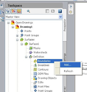
To add the boundary to a surface that has just been created, on the Prospector tab, go to Surfaces. Find and expand the newly created surface, expand Definition, right click Boundaries and select Add...


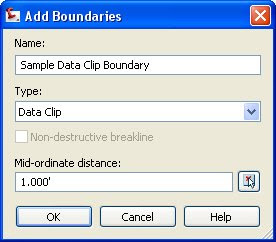
Set the boundary Type to Data Clip, press OK, and select the polyline that represents your data clip.


From here, create your surface as you normally would. The only difference is that any data outside the data clip boundary will be completely ignored and will not be loaded into memory when Civil 3D loads the surface. This feature will save you time and reduces crashes.


Saving memory when using Feature Lines


If you extensively use feature lines, knowing that they are continually looking at one another to detect crossings will help you understand why it can be helpful to place feature lines in different Civil 3D Sites.

When you go to edit, offset, move, or otherwise change a feature line, all the possible crossings of all feature line segments in that site must be checked by the program and that takes a lot of memory. Moving a feature line to its own site, can make functions that take many minutes take only seconds.


To move a feature line to another site, in the drawing window, select the feature line, right click, and select Move to Site


That's the end of Tim's first Civil 3D Blog entry. More to come...