
Autodesk Platinum Partner
Article by Timothy Corey
Many of our Civil 3D users want to realize the value of Subassembly Composer, but are spinning their wheels getting started. A common refrain is, "I know what it does, but the process of how to do it is just not clicking."
If that's you, stick with me through this primer.
Familiarize yourself with the Subassembly Composer user interface.

Tool Box, contains the tools you will use to place subassembly points, links and advanced decision making instructions.

Item 2 is the Flowchart. When you place a tool, you drag it from the Tool Box, you drop it in the Flowchart. As build your subassembly, the flowchart is where you'll interact with the various points, link and other tools you place. You will manage links between them here.

Below the Flowchart is Properties (Item 3 in the top image.) Each tool you place will have properties that control it. For example, when you place a point, its properties let you define where it is placed in reference to another point. Maybe you want to go ten feet at 25% slope. You will tell Subassembly Composer this in the Properties window.

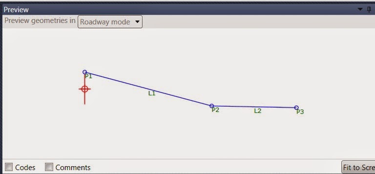
Item 4 is Preview. As you create more points and parameters, they will be displayed in the Preview as though you were viewing a cross section. Use Preview for reference, but be aware, as your subassemblies become more complicated, not all your points and links will display.
Picking a point or link in Preview will load its properties in the Properties window. This can be more intuitive than reading your way through the flowchart.
Item 5 is a combination window that includes Packet Settings, Input/output Parameters, Target Parameters, Superelevation and Event Viewer.
Go to Packet Settings tab to name your subassembly.

Input/output Parameters is where you define user-changeable values like slopes and offsets.

Target Parameters is where you define Surface, Offset and Elevation targets. If a point you place is supposed to intersect a surface, you will need a surface target. If you want a point to follow a feature line, 3d polyline, alignment or profile, you will need Offset and/or Elevation targets. We'll explain.

Create a subassembly that creates a point at pre-defined slope and x offset.
This is the most basic point you can create in Subassembly Composer, so it's a great place to start.
We are building a new road with travelway, curb and shoulder. For the travelway and curb, we have used existing Civil 3D subassemblies.

Our first custom subassembly will add a shoulder from the back of curb. The shoulder will be sloped away from the curb at five percent and will be ten feet wide.
In Subassembly Composer, drag a Point from the Tool Box to a place below the Start image in the Flowchart.

Now focus your attention below the Flowchart, to the Properties window. Point number will be P1 and will increment as you insert more points. This is the starting point of our shoulder subassembly and we will place our next point in reference to this point, P1.
In the Properties window for P1, note the From Point is automatically set to Origin and the Point Geometry Type is Delta X and Delta Y. Leave these values for this point.

If you want to place a point code here, you can, but in the example we are not placing a point code on this point because we plan to use a point code, supplied by the Curb subassembly and to which this point will be attached, for all drafting, reporting or modeling.
Now, drag another point from the Tool Box to the Flowchart. This will be P2 & L1. P stands for Point, L for Link. Notice the arrow pointing from P1 to P2 & L1. That shows you the connection between points.
In the Properties window, change the Type from Delta X and Delta Y to Slope and Delta X. We said the point will be sloped down at 5 percent and 10 feet right of the connection point, so we need to set the point creation type to match the value types we have. Take a moment and read the other types.
From Point should be set to P1. Set slope to -5%. If you don't want to enter the % sign, enter -.05. If you type 5 without the percent sign, you will get 500 percent. Optionally, you can type 5%. Type 10 for the offset.

Notice that for this point, we have entered a point code of "Shoulder." You must use the quotation marks to enter a string of text for the point code. If you do not want a link between points, you can scroll down and uncheck Add Link to From Point. You can optionally add multiple link codes like "Top" "Datum" "Pavement" Either be sure each is enclosed in quotes or put all inside one set of quotes, but add commas between: "Top, Datum, Pavement"
We're almost done with this most basic subassembly. Move to the Packet Settings tab and give your creation a name.

Then go to the upper left corner of Subassembly Composer and use SaveAs to save your packet file. Pay attention to where you put it.
Go back to Civil 3D where you have your assembly design started, ready to have the shoulder attached. On the Ribbon, go to Insert tab, click where it says Import in the Import panel. This will expose extra functions. Pick Import Subassemblies...


Attach it to the back of curb like you would any other subassembly. As you place the new subassembly, notice the settings in the Properties window.


Autodesk Civil 3D Certified Professional
Many of our Civil 3D users want to realize the value of Subassembly Composer, but are spinning their wheels getting started. A common refrain is, "I know what it does, but the process of how to do it is just not clicking."
If that's you, stick with me through this primer.
Familiarize yourself with the Subassembly Composer user interface.
Tool Box, contains the tools you will use to place subassembly points, links and advanced decision making instructions.
Item 2 is the Flowchart. When you place a tool, you drag it from the Tool Box, you drop it in the Flowchart. As build your subassembly, the flowchart is where you'll interact with the various points, link and other tools you place. You will manage links between them here.
Below the Flowchart is Properties (Item 3 in the top image.) Each tool you place will have properties that control it. For example, when you place a point, its properties let you define where it is placed in reference to another point. Maybe you want to go ten feet at 25% slope. You will tell Subassembly Composer this in the Properties window.
Item 4 is Preview. As you create more points and parameters, they will be displayed in the Preview as though you were viewing a cross section. Use Preview for reference, but be aware, as your subassemblies become more complicated, not all your points and links will display.
Picking a point or link in Preview will load its properties in the Properties window. This can be more intuitive than reading your way through the flowchart.
Item 5 is a combination window that includes Packet Settings, Input/output Parameters, Target Parameters, Superelevation and Event Viewer.
Go to Packet Settings tab to name your subassembly.
Input/output Parameters is where you define user-changeable values like slopes and offsets.
Target Parameters is where you define Surface, Offset and Elevation targets. If a point you place is supposed to intersect a surface, you will need a surface target. If you want a point to follow a feature line, 3d polyline, alignment or profile, you will need Offset and/or Elevation targets. We'll explain.
Create a subassembly that creates a point at pre-defined slope and x offset.
This is the most basic point you can create in Subassembly Composer, so it's a great place to start.
We are building a new road with travelway, curb and shoulder. For the travelway and curb, we have used existing Civil 3D subassemblies.
Our first custom subassembly will add a shoulder from the back of curb. The shoulder will be sloped away from the curb at five percent and will be ten feet wide.
In Subassembly Composer, drag a Point from the Tool Box to a place below the Start image in the Flowchart.
Now focus your attention below the Flowchart, to the Properties window. Point number will be P1 and will increment as you insert more points. This is the starting point of our shoulder subassembly and we will place our next point in reference to this point, P1.
In the Properties window for P1, note the From Point is automatically set to Origin and the Point Geometry Type is Delta X and Delta Y. Leave these values for this point.
If you want to place a point code here, you can, but in the example we are not placing a point code on this point because we plan to use a point code, supplied by the Curb subassembly and to which this point will be attached, for all drafting, reporting or modeling.
Now, drag another point from the Tool Box to the Flowchart. This will be P2 & L1. P stands for Point, L for Link. Notice the arrow pointing from P1 to P2 & L1. That shows you the connection between points.
In the Properties window, change the Type from Delta X and Delta Y to Slope and Delta X. We said the point will be sloped down at 5 percent and 10 feet right of the connection point, so we need to set the point creation type to match the value types we have. Take a moment and read the other types.
From Point should be set to P1. Set slope to -5%. If you don't want to enter the % sign, enter -.05. If you type 5 without the percent sign, you will get 500 percent. Optionally, you can type 5%. Type 10 for the offset.
Notice that for this point, we have entered a point code of "Shoulder." You must use the quotation marks to enter a string of text for the point code. If you do not want a link between points, you can scroll down and uncheck Add Link to From Point. You can optionally add multiple link codes like "Top" "Datum" "Pavement" Either be sure each is enclosed in quotes or put all inside one set of quotes, but add commas between: "Top, Datum, Pavement"
Then go to the upper left corner of Subassembly Composer and use SaveAs to save your packet file. Pay attention to where you put it.
Go back to Civil 3D where you have your assembly design started, ready to have the shoulder attached. On the Ribbon, go to Insert tab, click where it says Import in the Import panel. This will expose extra functions. Pick Import Subassemblies...
This location has been changed for 2016. Import Subassemblies has graduated from the dropdown to the main part of the Import panel.
For Source File, press the file folder icon to browse and select the .pkt file you just saved.
Pick the tool palette onto which the new subassembly should be placed.
So now you've imported your custom subassembly into AutoCAD Civil 3D. Here is it is on my Custom SubAssy's Tool Palette tab.
Attach it to the back of curb like you would any other subassembly. As you place the new subassembly, notice the settings in the Properties window.
There is some information being reported, but no settings can be changed. What if you want the user to be able to change the slope and offset values? That's where creating Input Parameters come in and that's the next lesson, Part Two.
1 comment:
Davidlevy is one of the most successful freelance composers, he is audio engineer
sound designer real PRO. David is form Austin, Texas and he works for Rooster
Teeth, composing music for Red vs.
Blue and doing sound design for RWBY. http://www.davidlevymusic.com he is great!
Post a Comment